PIC Tutorial Hardware - Extras
OUTPUTS
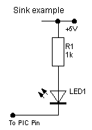
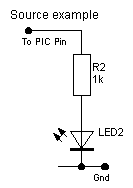
![]() I've
added this page to give a few extra simple interfacing examples, the PIC
itself inputs and outputs logic level signals, for the purposes of these
tutorials we can consider a 'high' output to be 5V, and a low output to be
0V. If you check the PIC datasheets, you will find that the output pins can
actually 'sink' or 'source' a reasonable amount of current - about 25mA or
so. 'Sink' means that the chip 'sinks' current down into itself, so the load
is connected from the positive rail to the I/O pin and the load is switched
ON by the pin going 'low'. 'Source' is just the reverse, the I/O pin is the
actual source of the current, and it flows out of the pin, through the load
down to ground - in this case the load is switched ON by the pin going
'high'.
I've
added this page to give a few extra simple interfacing examples, the PIC
itself inputs and outputs logic level signals, for the purposes of these
tutorials we can consider a 'high' output to be 5V, and a low output to be
0V. If you check the PIC datasheets, you will find that the output pins can
actually 'sink' or 'source' a reasonable amount of current - about 25mA or
so. 'Sink' means that the chip 'sinks' current down into itself, so the load
is connected from the positive rail to the I/O pin and the load is switched
ON by the pin going 'low'. 'Source' is just the reverse, the I/O pin is the
actual source of the current, and it flows out of the pin, through the load
down to ground - in this case the load is switched ON by the pin going
'high'.
![]() Most
of the examples in the tutorials use simple LED's, the 25mA capacity of the
PIC is more than sufficient to provide this current, so all that's required
is the LED itself, and a simple current limiting resistor - connecting the
LED without a resistor is likely to damage both the LED and the PIC!. The
two examples below show how to connect an LED in either 'sink' or 'source'
modes
Most
of the examples in the tutorials use simple LED's, the 25mA capacity of the
PIC is more than sufficient to provide this current, so all that's required
is the LED itself, and a simple current limiting resistor - connecting the
LED without a resistor is likely to damage both the LED and the PIC!. The
two examples below show how to connect an LED in either 'sink' or 'source'
modes
 |
 |
|
The LED will light when the PIC pin is low. |
The LED will light when the PIC pin is high. |
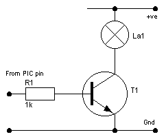
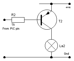
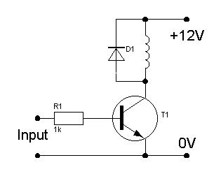
![]() This
is fine for lighting an LED, but for heavier loads such as relays, motors
etc. the 25mA current capacity of the PIC is too low, so we need a slightly
more complicated system to give greater capacity. Probably the simplest way
is to use a switching transistor, and, just as with the previous example, we
can 'sink' or 'source' the output. These first two transistor examples show
a small lamp being switched.
This
is fine for lighting an LED, but for heavier loads such as relays, motors
etc. the 25mA current capacity of the PIC is too low, so we need a slightly
more complicated system to give greater capacity. Probably the simplest way
is to use a switching transistor, and, just as with the previous example, we
can 'sink' or 'source' the output. These first two transistor examples show
a small lamp being switched.
 |
 |
|
|
|
![]() The
'sinking' example is probably the easiest to understand, as the PIC pin goes
high current flows through R1 turning the transistor ON, effectively
connecting the bottom end of the lamp to ground. This method has a rather
useful property, the +ve supply to the lamp isn't related in any way to the
supply voltage of the PIC, so you could quite happily have the PIC fed from
5V, and a 12V supply feeding the lamp, you just need to make sure that they
share a common 0V or Gnd connection.
The
'sinking' example is probably the easiest to understand, as the PIC pin goes
high current flows through R1 turning the transistor ON, effectively
connecting the bottom end of the lamp to ground. This method has a rather
useful property, the +ve supply to the lamp isn't related in any way to the
supply voltage of the PIC, so you could quite happily have the PIC fed from
5V, and a 12V supply feeding the lamp, you just need to make sure that they
share a common 0V or Gnd connection.
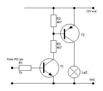
![]() The
'source' example is effectively the same but upside down, while the PIC
output is high no current flows through R2, so the transistor is turned OFF,
as the PIC pin goes low current flows through R2 as before turning the
transistor ON. This effectively connects the top of the lamp to the +ve
supply. Unlike the 'sink' example, this simple 'source' circuit must use the
same supply as the PIC - because for the PIC to turn the transistor OFF it's
output must go as high as the +ve supply to the emitter of the transistor.
The
'source' example is effectively the same but upside down, while the PIC
output is high no current flows through R2, so the transistor is turned OFF,
as the PIC pin goes low current flows through R2 as before turning the
transistor ON. This effectively connects the top of the lamp to the +ve
supply. Unlike the 'sink' example, this simple 'source' circuit must use the
same supply as the PIC - because for the PIC to turn the transistor OFF it's
output must go as high as the +ve supply to the emitter of the transistor.
|
|
 |
 |
INPUTS
![]() Inputs
to a PIC have the same 5V logic requirements, and just as outputs can be
'sink' or 'source', so the inputs can be active 'high' or active 'low'.
Basically this is just a variation on the same theme - but, depending on the
actual input device, you may be forced to use a particular method.
Inputs
to a PIC have the same 5V logic requirements, and just as outputs can be
'sink' or 'source', so the inputs can be active 'high' or active 'low'.
Basically this is just a variation on the same theme - but, depending on the
actual input device, you may be forced to use a particular method.
 |
 |
| Active LOW | Active HIGH |
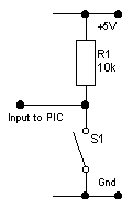
![]() These
are the two basic input alternatives, the 'Active LOW' example is the most
common, simply because the MicroChip PIC's usually have selectable 'weak
pullups' on some ports - so you don't always even need the 'pull up'
resistor R1. This is the configuration I've used in the tutorials, although
I include the 'pull up' resistors so you can use them on any port. It's very
easy to understand, the resistor R1 'pulls' the PIC input high (logic '1') -
when you press the switch it pulls the voltage down to zero, changing the
input to logic '0'.
These
are the two basic input alternatives, the 'Active LOW' example is the most
common, simply because the MicroChip PIC's usually have selectable 'weak
pullups' on some ports - so you don't always even need the 'pull up'
resistor R1. This is the configuration I've used in the tutorials, although
I include the 'pull up' resistors so you can use them on any port. It's very
easy to understand, the resistor R1 'pulls' the PIC input high (logic '1') -
when you press the switch it pulls the voltage down to zero, changing the
input to logic '0'.
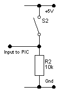
![]() The
'Active HIGH' example works in the opposite way, R2 is a 'pull down'
resistor, holding the PIC input at logic '0', pressing the switch connects
the PIC input to the 5V rail, forcing it to logic '1'.
The
'Active HIGH' example works in the opposite way, R2 is a 'pull down'
resistor, holding the PIC input at logic '0', pressing the switch connects
the PIC input to the 5V rail, forcing it to logic '1'.
![]() In
these first two examples I've shown switches (S1 and S2), but these could
just as easily be a switching transistor, or the output from an IC, or
simply an output pin from another PIC.
In
these first two examples I've shown switches (S1 and S2), but these could
just as easily be a switching transistor, or the output from an IC, or
simply an output pin from another PIC.
 |
 |
| Transistor switching LOW | Transistor switching HIGH |
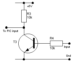
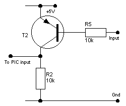
![]() These
two examples show how to use a switching transistor on the inputs, due to
the inverting action of the transistors, the left hand example pulls the PIC
pin LOW when the input to the transistor is HIGH. The right hand example
pulls the PIC pin HIGH, when it's input goes LOW. A very useful effect of
the left hand example is that the input doesn't need to be a 5V logic
signal, it could easily be a 12V signal (or higher), the action of T3
converts the input to a nice 5V signal for the PIC - as long as the input to
T3 is high enough to switch T3 ON.
These
two examples show how to use a switching transistor on the inputs, due to
the inverting action of the transistors, the left hand example pulls the PIC
pin LOW when the input to the transistor is HIGH. The right hand example
pulls the PIC pin HIGH, when it's input goes LOW. A very useful effect of
the left hand example is that the input doesn't need to be a 5V logic
signal, it could easily be a 12V signal (or higher), the action of T3
converts the input to a nice 5V signal for the PIC - as long as the input to
T3 is high enough to switch T3 ON.
![]() A
useful feature of the PIC inputs are the 'protection diodes', these clamp
the input to the +VE supply and GND, preventing the input going above +VE or
below GND. This means you can feed a higher voltage into the input, with
just a simple current limiting resistor, MicroChip have an application note
for a light dimmer, where the incoming mains is fed via such a limiting
resistor straight into a PIC input pin - used to detect the zero-crossing
point of the mains. The 16F628 datasheets quotes the maximum 'clamp current'
through the diodes as 20mA, but I would suggest keeping it far lower than
that, it's a high impedance input so we don't require much current through
the limiting resistor.
A
useful feature of the PIC inputs are the 'protection diodes', these clamp
the input to the +VE supply and GND, preventing the input going above +VE or
below GND. This means you can feed a higher voltage into the input, with
just a simple current limiting resistor, MicroChip have an application note
for a light dimmer, where the incoming mains is fed via such a limiting
resistor straight into a PIC input pin - used to detect the zero-crossing
point of the mains. The 16F628 datasheets quotes the maximum 'clamp current'
through the diodes as 20mA, but I would suggest keeping it far lower than
that, it's a high impedance input so we don't require much current through
the limiting resistor.