PIC Tutorial - Wireless Boards
Wireless Boards
![]() This
time we actually need two boards, one transmitter board, and a receiver
board as well. The licence free radio modules I'm using are from
RFSolutions,
the RTFQ1 (transmitter) and RRFQ1 (receiver), they are FM modules, with a
range of up to 250m, mine work on a frequency of 433.9MHz, and they are
available at low cost from a number of sources. I've provided a copy of the
datasheet if you want to have a read of
it.
This
time we actually need two boards, one transmitter board, and a receiver
board as well. The licence free radio modules I'm using are from
RFSolutions,
the RTFQ1 (transmitter) and RRFQ1 (receiver), they are FM modules, with a
range of up to 250m, mine work on a frequency of 433.9MHz, and they are
available at low cost from a number of sources. I've provided a copy of the
datasheet if you want to have a read of
it.
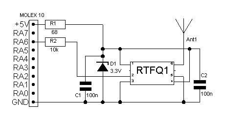
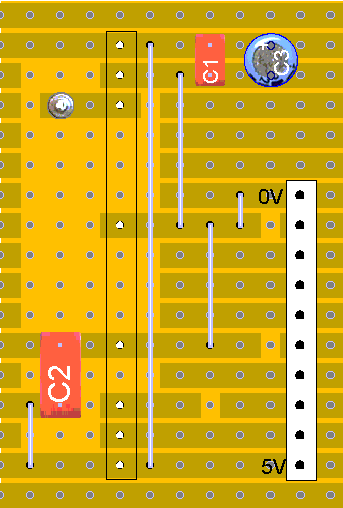
![]() The
transmitter works off a lower voltage, so we've got a small 3.3V zener diode
(D1) and a 68 ohm resistor as a regulator to provide it with 3.3V, a 10K
resistor to interface the 5V logic to the 3.3V logic, and there's a couple
of decoupling capacitors.
The
transmitter works off a lower voltage, so we've got a small 3.3V zener diode
(D1) and a 68 ohm resistor as a regulator to provide it with 3.3V, a 10K
resistor to interface the 5V logic to the 3.3V logic, and there's a couple
of decoupling capacitors.
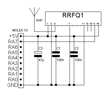
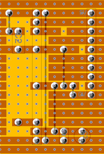
![]() The
receiver board is very straight forward, it's simply the module and a few
decoupling capacitors, there is an extra output available, which is an
analogue voltage related to the signal strength, but I've not connected
that.
The
receiver board is very straight forward, it's simply the module and a few
decoupling capacitors, there is an extra output available, which is an
analogue voltage related to the signal strength, but I've not connected
that.
![]() I used
these modules because they are low cost, and easily available, but there's
no urgent need to use these particular modules, any similar devices should
be fine, but the layouts will obviously be somewhat different.
I used
these modules because they are low cost, and easily available, but there's
no urgent need to use these particular modules, any similar devices should
be fine, but the layouts will obviously be somewhat different.
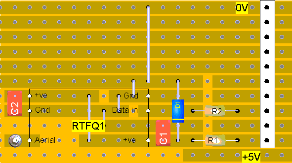 |
|
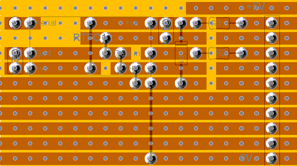 |
|
 |
|
 |
|
![]() For
anyone who's interested, I'm now using Abacom products for my diagrams, 'sPlan
5.0' for the circuits, and 'LochMaster 3.0' for the layouts.
For
anyone who's interested, I'm now using Abacom products for my diagrams, 'sPlan
5.0' for the circuits, and 'LochMaster 3.0' for the layouts.