PIC Tutorial - Switch Board
Switch Board

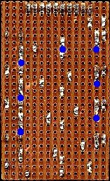
![]() This
is the Switch Board, a simple array of four pushbutton switches connected
to the top four pins of one
port, with four LED's connected to the bottom four pins of the same port
(so you don't require the LED board as well). The switches connect to the top four pins of PortA, this is because
RA5 can only be an input, and RA4 is an open-collector output - by using
the top four pins it leaves the others available as general purpose I/O
pins. Although it's labelled as connecting to PortA, it can also be
connected to PortB if required.
This
is the Switch Board, a simple array of four pushbutton switches connected
to the top four pins of one
port, with four LED's connected to the bottom four pins of the same port
(so you don't require the LED board as well). The switches connect to the top four pins of PortA, this is because
RA5 can only be an input, and RA4 is an open-collector output - by using
the top four pins it leaves the others available as general purpose I/O
pins. Although it's labelled as connecting to PortA, it can also be
connected to PortB if required.
 |
|
 |