PIC Tutorial - Stepper Board
Stepper Board
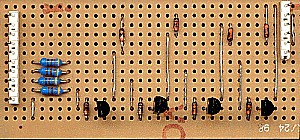
![]() This is
the Stepper Board, it contains four transistor drivers for feeding a uni-polar
stepper motor, such as those commonly found in old 5.25 inch floppy drives
and printers. The transistors are fed via 470 ohm resistors, to limit the
base current, and the eight diodes are there to absorb the back EMF (Electro
Motive Force) from the stepper motor coils when they turn off - when you
turn an inductor off, be it a motor or relay, it generates a high reverse
voltage spike (which is how car ignition coils work) - this would be likely
to damage the transistors, the diodes prevent it. The stepper motor itself
consists of two centre-tapped windings, with the centre-taps connected to
the positive supply rail, to make the motor move you need to activate the
coils in a certain sequence, it then moves one step for each value in the
sequence - a half-stepping mode is also available, which gives double the
number of steps by using a slightly different sequence. The wiring of the 6
pin connector to the motor is how the two motors I have are wired, one was
from an old floppy, the other is an Epson printer motor - both are wired the
same way on similar 6 pin connectors - not all motors are likely to be wired
exactly the same though!. I've marked the connections to the motor as A, B,
C and D, plus two marked '+', these are connected to the positive supply,
and to make the motor step the other four are grounded in a particular
sequence. The simplest sequence is to select them one at a time, A, B, C
then D, this produces 4 steps in a clockwise direction - to produce one full
rotation this needs to be repeated 50 times as my particular motor has 200
steps per revolution, giving 1.8 degrees resolution (in full step mode).
This is
the Stepper Board, it contains four transistor drivers for feeding a uni-polar
stepper motor, such as those commonly found in old 5.25 inch floppy drives
and printers. The transistors are fed via 470 ohm resistors, to limit the
base current, and the eight diodes are there to absorb the back EMF (Electro
Motive Force) from the stepper motor coils when they turn off - when you
turn an inductor off, be it a motor or relay, it generates a high reverse
voltage spike (which is how car ignition coils work) - this would be likely
to damage the transistors, the diodes prevent it. The stepper motor itself
consists of two centre-tapped windings, with the centre-taps connected to
the positive supply rail, to make the motor move you need to activate the
coils in a certain sequence, it then moves one step for each value in the
sequence - a half-stepping mode is also available, which gives double the
number of steps by using a slightly different sequence. The wiring of the 6
pin connector to the motor is how the two motors I have are wired, one was
from an old floppy, the other is an Epson printer motor - both are wired the
same way on similar 6 pin connectors - not all motors are likely to be wired
exactly the same though!. I've marked the connections to the motor as A, B,
C and D, plus two marked '+', these are connected to the positive supply,
and to make the motor step the other four are grounded in a particular
sequence. The simplest sequence is to select them one at a time, A, B, C
then D, this produces 4 steps in a clockwise direction - to produce one full
rotation this needs to be repeated 50 times as my particular motor has 200
steps per revolution, giving 1.8 degrees resolution (in full step mode).
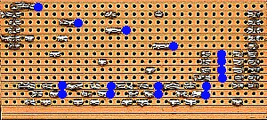
![]() The
jumper J1 can be used to feed the motor from the 5V supply, and this should
be fine just for experimenting, but the motors are designed for 12V, and
won't produce much power from 5V - by disconnecting J1 you can feed a 12V
supply to the top of D5, D6, D7 and D8 - obviously if you don't disconnect
J1 you are very likely to fry the PIC!.
The
jumper J1 can be used to feed the motor from the 5V supply, and this should
be fine just for experimenting, but the motors are designed for 12V, and
won't produce much power from 5V - by disconnecting J1 you can feed a 12V
supply to the top of D5, D6, D7 and D8 - obviously if you don't disconnect
J1 you are very likely to fry the PIC!.
 |
|
 |
|