PIC Tutorial Main Board
Main Board
![]() This
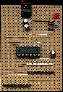
is the circuit of the main board for the tutorials, it consists of the
PIC16F628, a 7805 regulator, 3 capacitors, three ten pin connectors, one
for PortA, and two for PortB (the second for connecting two of these
boards together), and a two pin ground test connection - optionally it also includes an LED, a
resistor, and two 2 pin jumpers. Each of the three ten pin connectors is wired
identically, with a ground connection at the left side, and a 5V
connection at the right - this will allow you to plug the same extension
board into either port, and help to demonstrate their differences. The
capacitors C1 and C2 are to keep the 7805 stable, they have a tendency to
oscillate without them, and C3 is just a decoupling capacitor placed near
the chip, always a good practice (although PIC's do seem very tolerant of
them). The jumpers J1 and J2 allow the LED to be connected either to 5V
(J2) as a 'power on' indicator, or to RB7 (J1) where it can be switched by
the port pin - this allows you to do something before you build any
further boards. Under no circumstances connect both J1 and J2 at the
same time, it's likely to damage the chip.
This
is the circuit of the main board for the tutorials, it consists of the
PIC16F628, a 7805 regulator, 3 capacitors, three ten pin connectors, one
for PortA, and two for PortB (the second for connecting two of these
boards together), and a two pin ground test connection - optionally it also includes an LED, a
resistor, and two 2 pin jumpers. Each of the three ten pin connectors is wired
identically, with a ground connection at the left side, and a 5V
connection at the right - this will allow you to plug the same extension
board into either port, and help to demonstrate their differences. The
capacitors C1 and C2 are to keep the 7805 stable, they have a tendency to
oscillate without them, and C3 is just a decoupling capacitor placed near
the chip, always a good practice (although PIC's do seem very tolerant of
them). The jumpers J1 and J2 allow the LED to be connected either to 5V
(J2) as a 'power on' indicator, or to RB7 (J1) where it can be switched by
the port pin - this allows you to do something before you build any
further boards. Under no circumstances connect both J1 and J2 at the
same time, it's likely to damage the chip.
 |
|
 |