PIC Tutorial Main Board Three
Main Board Three
![]() This
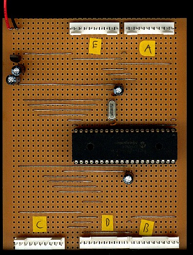
is the circuit of the third main board for the tutorials, it consists of the
PIC16F877, a 7805 regulator, a 20MHz crystal, 6 capacitors, five ten pin
connectors, one for PortA, one for PortB, one for PortC, one for PortD and
one for PortE . Each of the
five ten pin connectors is wired identically, with a ground connection at
the left side, and a 5V connection at the right - this will allow you to
plug the same extension board into any port, and help to demonstrate their differences
- the most obvious differences are that PortA only has 6 I/O lines, which
can be either digital I/O or analogue inputs, with 10 bit resolution, and
that Port E only has 3 I/O lines.
This
is the circuit of the third main board for the tutorials, it consists of the
PIC16F877, a 7805 regulator, a 20MHz crystal, 6 capacitors, five ten pin
connectors, one for PortA, one for PortB, one for PortC, one for PortD and
one for PortE . Each of the
five ten pin connectors is wired identically, with a ground connection at
the left side, and a 5V connection at the right - this will allow you to
plug the same extension board into any port, and help to demonstrate their differences
- the most obvious differences are that PortA only has 6 I/O lines, which
can be either digital I/O or analogue inputs, with 10 bit resolution, and
that Port E only has 3 I/O lines.
![]() Basically
it's very similar to the 16F628 tutorial board, but has extra ports and
added facilities - as the 16F877 doesn't have an internal oscillator a
crystal is required for the clock oscillator - I choose a 20MHz crystal
for this, if you can't get a 20MHz chip the 4MHz 16F877's seem perfectly
happy to run at 20MHz - I suspect they are exactly the same chip, and
graded to provide the two different versions.
Basically
it's very similar to the 16F628 tutorial board, but has extra ports and
added facilities - as the 16F877 doesn't have an internal oscillator a
crystal is required for the clock oscillator - I choose a 20MHz crystal
for this, if you can't get a 20MHz chip the 4MHz 16F877's seem perfectly
happy to run at 20MHz - I suspect they are exactly the same chip, and
graded to provide the two different versions.
![]() I
used a 100mA regulator IC, a 78L05 - because I happened to have one, but a
7805 1A regulator would do just as well, and give more power availability
for extension boards.
I
used a 100mA regulator IC, a 78L05 - because I happened to have one, but a
7805 1A regulator would do just as well, and give more power availability
for extension boards.
 |
|
 |