PIC Tutorial - LCD Board
LCD Board
| Pin | Function | Description |
| 1 | Vss | Ground |
| 2 | Vdd | +ve supply |
| 3 | Vee | Contrast |
| 4 | RS | Register Select |
| 5 | R/W | Read/Write |
| 6 | E | Enable |
| 7 | D0 | Data bit 0 (8 bit) |
| 8 | D1 | Data bit 1 (8 bit) |
| 9 | D2 | Data bit 2 (8 bit) |
| 10 | D3 | Data bit 3 (8 bit) |
| 11 | D4 | Data bit 4 |
| 12 | D5 | Data bit 5 |
| 13 | D6 | Data bit 6 |
| 14 | D7 | Data bit 7 |
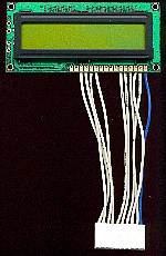
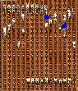
![]() This
is the LCD Board, using an LCD module based on the industry standard
Hitachi HD44780, it connects to 7 pins of one
port, and operates in 4 bit 'nibble' mode to save I/O pins. By connecting
to PortA we have to use a pull-up resistor (R1) on RA4, and are unable to
use RA5 (which is only an input), however this frees all of PortB which
will allow us to use some of the extra hardware available on PortB, along
with the LCD, in a later tutorial. The potentiometer P1, is for adjusting
the contrast of the display, and if incorrectly adjusted can cause the
display to be invisible. Although it's labelled as connecting to PortA, as
with most of the boards, it can also be
connected to PortB if required. By using 4 bit mode we can connect the
entire LCD module to one port, it uses exactly 10 pins (just right for our
Molex connectors). In 4 bit mode we don't use pins 7-10, which are used as
the lower 4 data bits in 8 bit mode, instead we write (or read) to the
upper 4 pins twice, transferring half of the data each time - this makes
the program slightly more complicated, but is well worth it for the pins
saved - particularly as it allows us to use just the one 10 pin connector.
This
is the LCD Board, using an LCD module based on the industry standard
Hitachi HD44780, it connects to 7 pins of one
port, and operates in 4 bit 'nibble' mode to save I/O pins. By connecting
to PortA we have to use a pull-up resistor (R1) on RA4, and are unable to
use RA5 (which is only an input), however this frees all of PortB which
will allow us to use some of the extra hardware available on PortB, along
with the LCD, in a later tutorial. The potentiometer P1, is for adjusting
the contrast of the display, and if incorrectly adjusted can cause the
display to be invisible. Although it's labelled as connecting to PortA, as
with most of the boards, it can also be
connected to PortB if required. By using 4 bit mode we can connect the
entire LCD module to one port, it uses exactly 10 pins (just right for our
Molex connectors). In 4 bit mode we don't use pins 7-10, which are used as
the lower 4 data bits in 8 bit mode, instead we write (or read) to the
upper 4 pins twice, transferring half of the data each time - this makes
the program slightly more complicated, but is well worth it for the pins
saved - particularly as it allows us to use just the one 10 pin connector.
 |
||||
 |
||||
|
||||