PIC Tutorial - Keypad Board
Keypad Board
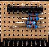
![]() This
is the Keypad Board, a very simple board for connecting a matrix keypad.
It consisted of only 4 resistors (used as pull-ups for the input lines),
and two connectors - one to the processor board, and the other for the
keypad to plug into, I used half a 16 pin DIL socket for this. Although it's labelled as connecting to
PortB, it can also be
connected to PortA if required.
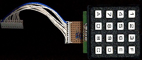
This
is the Keypad Board, a very simple board for connecting a matrix keypad.
It consisted of only 4 resistors (used as pull-ups for the input lines),
and two connectors - one to the processor board, and the other for the
keypad to plug into, I used half a 16 pin DIL socket for this. Although it's labelled as connecting to
PortB, it can also be
connected to PortA if required.
 |
|
 |
|
 |
|