PIC Tutorial - Joystick Board
Joystick Board
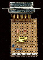
![]() This
is the Joystick Board, used for connecting a standard PC analogue joystick.
It connects to
4 pins of one port and uses a simple capacitor charging technique to read
the analogue resistance of the joystick. The circuit is nice and simple,
R1 and R2 are pull-up resistors for the two trigger buttons on the
joystick (which connect either pin 2 or pin 7 of the 15 way D connector to
ground). The analogue inputs are on pins 3 and 6, and consist of 100K
variable resistors from these pins to pin 1 (the 5V supply). From the
analogue controls we feed through R3 or R4, these are to set the minimum
resistance (2.2K when the joystick controls are at minimum). The current
through these resistors is used to charge C2 (or C1), and the charging
time is dependent on the value of the joystick + R3 (or R4). To read the
controls we discharge the capacitor (by setting the relevant port pin to
an output and setting it low), then reset the port pin to be an input and
wait until the capacitor charges enough to make the input switch high -
during this time we maintain a 16 bit count - this gives us a value based
on the position of the joystick.
This
is the Joystick Board, used for connecting a standard PC analogue joystick.
It connects to
4 pins of one port and uses a simple capacitor charging technique to read
the analogue resistance of the joystick. The circuit is nice and simple,
R1 and R2 are pull-up resistors for the two trigger buttons on the
joystick (which connect either pin 2 or pin 7 of the 15 way D connector to
ground). The analogue inputs are on pins 3 and 6, and consist of 100K
variable resistors from these pins to pin 1 (the 5V supply). From the
analogue controls we feed through R3 or R4, these are to set the minimum
resistance (2.2K when the joystick controls are at minimum). The current
through these resistors is used to charge C2 (or C1), and the charging
time is dependent on the value of the joystick + R3 (or R4). To read the
controls we discharge the capacitor (by setting the relevant port pin to
an output and setting it low), then reset the port pin to be an input and
wait until the capacitor charges enough to make the input switch high -
during this time we maintain a 16 bit count - this gives us a value based
on the position of the joystick.
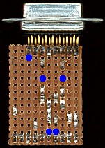
![]() Although it's labelled as connecting to PortB, as
with most of the boards, it can also be
connected to PortA if required.
Although it's labelled as connecting to PortB, as
with most of the boards, it can also be
connected to PortA if required.
 |
|
 |
|