PIC Tutorial - Infrared Board
Infrared Board
![]() This
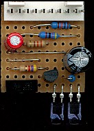
is the Infrared Board, we need two of these, so that we can communicate
between two main boards, it consists of two distinct parts. Firstly the IR
receiver, comprising R1, R2, C1, and the IR receiver I/C itself (feeding
port pin 2), and secondly the IR transmitter, comprising Q1, R3, R4,
R5,C2, IR1, and IR2 (fed from port pin 1). If you only want to do one way
communication you could build just the transmitter on one board, and just
the receiver on the other, but building both on both boards gives the
possibility of two way communication.
This
is the Infrared Board, we need two of these, so that we can communicate
between two main boards, it consists of two distinct parts. Firstly the IR
receiver, comprising R1, R2, C1, and the IR receiver I/C itself (feeding
port pin 2), and secondly the IR transmitter, comprising Q1, R3, R4,
R5,C2, IR1, and IR2 (fed from port pin 1). If you only want to do one way
communication you could build just the transmitter on one board, and just
the receiver on the other, but building both on both boards gives the
possibility of two way communication.
![]() The
receiver I/C detects IR signals modulated with a 38KHz signal, R2 and C1
are to provide decoupling for the supply (to avoid instability problems),
and R1 is just a pull-up resistor as the I/C has an open-collector output
(just like RA4 on the PIC).
The
receiver I/C detects IR signals modulated with a 38KHz signal, R2 and C1
are to provide decoupling for the supply (to avoid instability problems),
and R1 is just a pull-up resistor as the I/C has an open-collector output
(just like RA4 on the PIC).
![]() The
transmitter is a simple single transistor digital switch, when pin RB1
goes high this turns the transistor on, passing current through the IR
LED's, with the current limited by R5 between the LED's. This passes
quite a high current through the LED's and it's important that they are
pulsed and not left on permanently or damage will probably occur - C2 is
fitted to provide the required high current pulses without upsetting the
main 5V rail. By pulsing the LED's with high current we increase the range
and lower the current requirements - this is standard practice in IR
remote controls, R5 limits the current through the LED's. As the receiver
detects 38KHz modulation, we need to pulse the LED's at 38KHz, this can be
done by feeding the LED's with a 13uS pulse followed by a 13uS space - in
actual fact I decrease the pulse length, and increase the space length
(keeping the total length at 26uS) - this reduces the power consumption.
The
transmitter is a simple single transistor digital switch, when pin RB1
goes high this turns the transistor on, passing current through the IR
LED's, with the current limited by R5 between the LED's. This passes
quite a high current through the LED's and it's important that they are
pulsed and not left on permanently or damage will probably occur - C2 is
fitted to provide the required high current pulses without upsetting the
main 5V rail. By pulsing the LED's with high current we increase the range
and lower the current requirements - this is standard practice in IR
remote controls, R5 limits the current through the LED's. As the receiver
detects 38KHz modulation, we need to pulse the LED's at 38KHz, this can be
done by feeding the LED's with a 13uS pulse followed by a 13uS space - in
actual fact I decrease the pulse length, and increase the space length
(keeping the total length at 26uS) - this reduces the power consumption.
![]() Although it's labelled as connecting to PortB, as
with most of the boards, it can also be
connected to PortA if required.
Although it's labelled as connecting to PortB, as
with most of the boards, it can also be
connected to PortA if required.
 |
|
 |