PIC Tutorial - I2C Switch Board
I2C EEPROM Board
![]() This
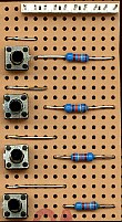
is the I2C Switch Board, although it's not really an I2C based board, I've
named it as such because it's intended to provide some input buttons for
the other I2C boards. As those boards use RB6 and RB7 for the I2C bus we
can't use the original switch board, however this board only has switches
(no LED's like the original switch board), and they connect to the bottom
four port pins. It plugs in to the second connector for PortB, the first
being used for the relevant I2C board.
This
is the I2C Switch Board, although it's not really an I2C based board, I've
named it as such because it's intended to provide some input buttons for
the other I2C boards. As those boards use RB6 and RB7 for the I2C bus we
can't use the original switch board, however this board only has switches
(no LED's like the original switch board), and they connect to the bottom
four port pins. It plugs in to the second connector for PortB, the first
being used for the relevant I2C board.
![]() The
first use of this board is to provide adjustment buttons for the I2C Clock
Board, enabling easy adjustment of the time and date. It will also be used
with the I2C A2D board, to allow various adjustments and settings to made,
such as 'set the sample time', 'dump data to PC' etc. I think most
projects can benefit from the availability of a few push buttons to
control their action.
The
first use of this board is to provide adjustment buttons for the I2C Clock
Board, enabling easy adjustment of the time and date. It will also be used
with the I2C A2D board, to allow various adjustments and settings to made,
such as 'set the sample time', 'dump data to PC' etc. I think most
projects can benefit from the availability of a few push buttons to
control their action.
![]() Although it's labelled as connecting to PortB, as
with most of the boards, it can also be
connected to PortA if required.
Although it's labelled as connecting to PortB, as
with most of the boards, it can also be
connected to PortA if required.
 |
|
 |