PIC Tutorial - I2C Clock Board
I2C Clock Board

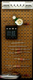
![]() This
is the I2C Clock Board, it uses a PCF8583P, which is a real time, battery
backed, CMOS I2C clock chip in an 8 pin DIL package. The actual chip I'm using here (as shown in
the picture) is labelled 'Intersil 7313', and came from a Grundig VS920
video recorder, but it's pin compatible with the original Philips chip
(which is what's actually listed on the circuit). Notice that this chip
only has one address line, so can only be mapped as either page 0, or page
1.
This
is the I2C Clock Board, it uses a PCF8583P, which is a real time, battery
backed, CMOS I2C clock chip in an 8 pin DIL package. The actual chip I'm using here (as shown in
the picture) is labelled 'Intersil 7313', and came from a Grundig VS920
video recorder, but it's pin compatible with the original Philips chip
(which is what's actually listed on the circuit). Notice that this chip
only has one address line, so can only be mapped as either page 0, or page
1.
![]() The
circuit is very similar to the previous I2C EEPROM board, with a few
additions, a 32KHz clock crystal and trimmer (using two of the previous
address lines), an extra alarm output complete with 12K pull-up resistor
(connected to RB4), and components for the battery backup circuit (D1 and
D2 are isolating diodes). When the board is powered up the chip is
supplied with 5V through D1 (which drops 0.7V leaving 4.3V on the chip),
D2 is reverse biased and passes no current. When the board isn't powered,
D2 passes current from the battery (only around 2uA, giving a long battery
life) to the chip, and D1 is reverse biased, isolated the rest of the
circuit. The 3V battery shown is a lithium disk type, and usually lasts
around 5 years in the Grundig VCR's that use this same chip. The trimmer
is for setting the accuracy of the clock, and if accurately adjusted
should keep good time.
The
circuit is very similar to the previous I2C EEPROM board, with a few
additions, a 32KHz clock crystal and trimmer (using two of the previous
address lines), an extra alarm output complete with 12K pull-up resistor
(connected to RB4), and components for the battery backup circuit (D1 and
D2 are isolating diodes). When the board is powered up the chip is
supplied with 5V through D1 (which drops 0.7V leaving 4.3V on the chip),
D2 is reverse biased and passes no current. When the board isn't powered,
D2 passes current from the battery (only around 2uA, giving a long battery
life) to the chip, and D1 is reverse biased, isolated the rest of the
circuit. The 3V battery shown is a lithium disk type, and usually lasts
around 5 years in the Grundig VCR's that use this same chip. The trimmer
is for setting the accuracy of the clock, and if accurately adjusted
should keep good time.
![]() Although it's labelled as connecting to PortB, as
with most of the boards, it can also be
connected to PortA if required.
Although it's labelled as connecting to PortB, as
with most of the boards, it can also be
connected to PortA if required.
 |
|
 |