PIC Tutorial - I2C EEPROM Board
I2C EEPROM Board
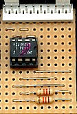
![]() This
is the I2C (or IIC) Board, it stands for 'Inter I/C Communications' and is
a standard two wire bidirectional bus used for communicating between chips
in most modern electronic equipment - for instance in a modern TV receiver
almost everything is controlled via I2C, and all the settings are usually
stored in a small 8 pin EEPROM (Electrically Erasable Read Only Memory).
This project uses a standard
EEPROM, and can be various types, which will all drop in the socket. The two signals to the chip are called SDA (Serial
DatA) and SCL (Serial CLock), and are open-collector outputs (like the
infamous RA4), but we can easily simulate that in software - and in any
case, we don't need to do so for the SCL signal for a 'single master
system', which is what we will be using. As we are only using a 'single
master' system, resistor R1 isn't really needed, but I've included it as a
matter of form.
This
is the I2C (or IIC) Board, it stands for 'Inter I/C Communications' and is
a standard two wire bidirectional bus used for communicating between chips
in most modern electronic equipment - for instance in a modern TV receiver
almost everything is controlled via I2C, and all the settings are usually
stored in a small 8 pin EEPROM (Electrically Erasable Read Only Memory).
This project uses a standard
EEPROM, and can be various types, which will all drop in the socket. The two signals to the chip are called SDA (Serial
DatA) and SCL (Serial CLock), and are open-collector outputs (like the
infamous RA4), but we can easily simulate that in software - and in any
case, we don't need to do so for the SCL signal for a 'single master
system', which is what we will be using. As we are only using a 'single
master' system, resistor R1 isn't really needed, but I've included it as a
matter of form.
![]() I
haven't labelled the EEPROM chip, as it can be a number of different ones,
basically the 24C02 (256 bytes), 24C04 (512 bytes), 24C08 (1024 bytes) or
24C16 (2048 bytes), these all use 'standard addressing', you can also use
a 24C32 (4096 bytes) or 24LC64 (8192 bytes) which use 'extended addressing' to
access the greater memory. On the smaller chips memory is in 256 byte
'pages', with standard addressing only allowing 8 pages. The page
addressing is also related to the address lines A0, A1 & A2, the 24C02
uses all three lines, so you can have eight connected to the bus with the
addresses set differently, the 24C04 only uses two address lines, allowing
4 chips to be connected. The 24C16 uses none of the address lines, it
already has all eight pages internally, so only one 24C16 can be connected
to the same I2C bus. So 'standard addressing' only allows 2048 bytes to be
addressed, in eight 256 byte 'pages'. The 'extended addressing' mode on
the larger chips uses two eight bit address registers (giving a possible
65,536 bytes per chip), plus the same three bit page/address allocation,
so you can have up to eight of these larger chips on the same bus. A
24LC256 is also available, which gives 32,768 bytes of space, and you can
also address 8 of these on the same I2C bus, giving 262,144 bytes of
memory storage which would make a very useful data-logger (over 72 hours
at one sample per second!).
I
haven't labelled the EEPROM chip, as it can be a number of different ones,
basically the 24C02 (256 bytes), 24C04 (512 bytes), 24C08 (1024 bytes) or
24C16 (2048 bytes), these all use 'standard addressing', you can also use
a 24C32 (4096 bytes) or 24LC64 (8192 bytes) which use 'extended addressing' to
access the greater memory. On the smaller chips memory is in 256 byte
'pages', with standard addressing only allowing 8 pages. The page
addressing is also related to the address lines A0, A1 & A2, the 24C02
uses all three lines, so you can have eight connected to the bus with the
addresses set differently, the 24C04 only uses two address lines, allowing
4 chips to be connected. The 24C16 uses none of the address lines, it
already has all eight pages internally, so only one 24C16 can be connected
to the same I2C bus. So 'standard addressing' only allows 2048 bytes to be
addressed, in eight 256 byte 'pages'. The 'extended addressing' mode on
the larger chips uses two eight bit address registers (giving a possible
65,536 bytes per chip), plus the same three bit page/address allocation,
so you can have up to eight of these larger chips on the same bus. A
24LC256 is also available, which gives 32,768 bytes of space, and you can
also address 8 of these on the same I2C bus, giving 262,144 bytes of
memory storage which would make a very useful data-logger (over 72 hours
at one sample per second!).
| ChipType | Address | ||||||
| 1 | 0 | 1 | 0 | x | x | x | R/W |
![]() Each I2C chip type has it's own individual 4 bit chip
address, for EEPROM memory chips it's
'1010', this is combined with a 3 bit address from the address input pins
to give a 7 bit unique chip address - this is then made into an 8 bit word
by the addition of a R/W bit, '1' for read' and '0' for write, and this is
the complete value written as the 'Slave Address' for the chip. Each chip
on the bus must have a unique address or problems are going to occur.
Each I2C chip type has it's own individual 4 bit chip
address, for EEPROM memory chips it's
'1010', this is combined with a 3 bit address from the address input pins
to give a 7 bit unique chip address - this is then made into an 8 bit word
by the addition of a R/W bit, '1' for read' and '0' for write, and this is
the complete value written as the 'Slave Address' for the chip. Each chip
on the bus must have a unique address or problems are going to occur.
![]() Although it's labelled as connecting to PortB, as
with most of the boards, it can also be
connected to PortA if required.
Although it's labelled as connecting to PortB, as
with most of the boards, it can also be
connected to PortA if required.
 |
|
 |