PIC Tutorial - I2C A2D Board
I2C A2D Board
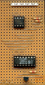
![]() This
is the I2C A2D (Analogue to Digital converter) Board, it uses a Philips PCF8591P,
which is an I2C chip providing 4 analogue inputs, and 1 analogue output,
all having 8 bit resolution. There are actually very few support
components required, I've chosen to use an external 2.5V precision voltage
reference, which feeds in at pin 14, but this could be simply connected to
the 5V rail - though it would be less accurate. By using the 2.5V
reference we set the range of the conversion from 0-2.5V, however this can
easily be scaled by feeding from a suitable attenuator. Notice the circuit
also shows an EEPROM, the idea being to give the option of storing samples
in it's non-volatile memory, and I'll be using a 24C256 to give 32,768
bytes of storage. Notice both chips connect to the same port pins via the
I2C bus - by having different chip addresses we can address either one
independently.
This
is the I2C A2D (Analogue to Digital converter) Board, it uses a Philips PCF8591P,
which is an I2C chip providing 4 analogue inputs, and 1 analogue output,
all having 8 bit resolution. There are actually very few support
components required, I've chosen to use an external 2.5V precision voltage
reference, which feeds in at pin 14, but this could be simply connected to
the 5V rail - though it would be less accurate. By using the 2.5V
reference we set the range of the conversion from 0-2.5V, however this can
easily be scaled by feeding from a suitable attenuator. Notice the circuit
also shows an EEPROM, the idea being to give the option of storing samples
in it's non-volatile memory, and I'll be using a 24C256 to give 32,768
bytes of storage. Notice both chips connect to the same port pins via the
I2C bus - by having different chip addresses we can address either one
independently.
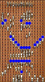
![]() Although it's labelled as connecting to PortB, as
with most of the boards, it can also be
connected to PortA if required.
Although it's labelled as connecting to PortB, as
with most of the boards, it can also be
connected to PortA if required.
 |
|
 |