PIC Tutorial - Analogue Board
Analogue Input Board

![]() This is
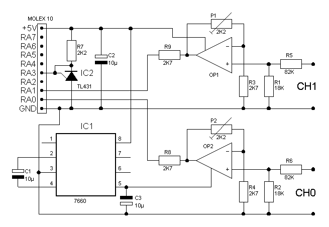
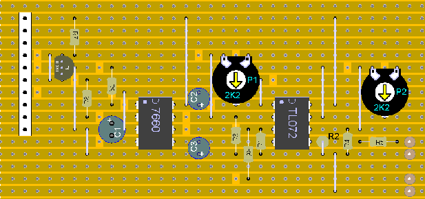
the Analogue Input Board, intended for use with the 16F876 and 16F877
boards, it provides adjustable buffered inputs for AD0 and AD1, plus a
precision voltage reference on AD3, to give a positive reference of 2.5V. As
we're using op-amps for the buffers, we require a negative voltage rail - as
we don't have one on the tutorial boards we're using a 7660 I/C to generate
one. The presets on each channel allow us to alter the gain, from a gain of
unity, to a little below two times, the input attenuators R5/R1 and R6/R2,
divide the incoming voltage by about 4.5 - so with a reference of 2.5V this
gives us a minimum sensitivity of 9V. By using the presets, P1 and P2, we
can adjust the gain so that 10.23V at the input gives 2.5V at the output,
this avoids any calculations in converting the reading to a voltage. If
required, R5 and R6 can be increased, to give a higher voltage range.
This is
the Analogue Input Board, intended for use with the 16F876 and 16F877
boards, it provides adjustable buffered inputs for AD0 and AD1, plus a
precision voltage reference on AD3, to give a positive reference of 2.5V. As
we're using op-amps for the buffers, we require a negative voltage rail - as
we don't have one on the tutorial boards we're using a 7660 I/C to generate
one. The presets on each channel allow us to alter the gain, from a gain of
unity, to a little below two times, the input attenuators R5/R1 and R6/R2,
divide the incoming voltage by about 4.5 - so with a reference of 2.5V this
gives us a minimum sensitivity of 9V. By using the presets, P1 and P2, we
can adjust the gain so that 10.23V at the input gives 2.5V at the output,
this avoids any calculations in converting the reading to a voltage. If
required, R5 and R6 can be increased, to give a higher voltage range.
![]() If using
the voltage reference, which we should - as the op-amps won't feed
rail-to-rail - we can only use this board on PortA. As we're using pins 0
and 1, we could connect to PortE on an 877, but there's no reference voltage
input on PortE.
If using
the voltage reference, which we should - as the op-amps won't feed
rail-to-rail - we can only use this board on PortA. As we're using pins 0
and 1, we could connect to PortE on an 877, but there's no reference voltage
input on PortE.
![]() For
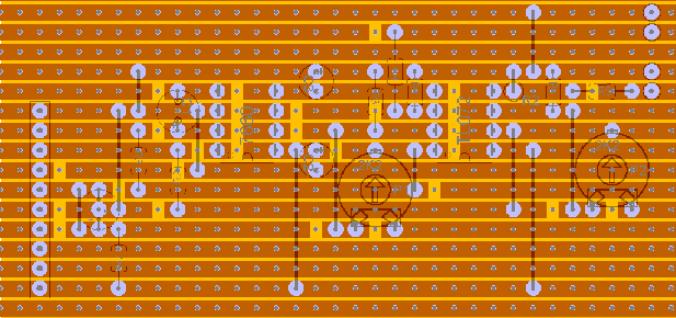
anyone who's interested, I'm now using Abacom products for my diagrams, 'sPlan
5.0' for the circuits, and 'LochMaster 3.0' for the layouts.
For
anyone who's interested, I'm now using Abacom products for my diagrams, 'sPlan
5.0' for the circuits, and 'LochMaster 3.0' for the layouts.

