PIC Tutorial - 7 Segment LED Board
7 Segment LED Board
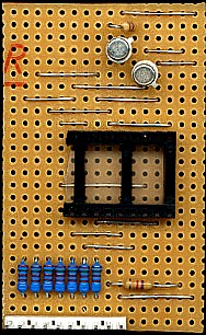
![]() This is
the 7 Segment LED Board, a board containing a dual 7 segment LED display (a
Kingbright DA56-11EWA, Maplin code BY66W). The display is a common
anode type, so to light a segment we need to take the relevant segment low.
A dual 7 segment display like this requires 14 I/O lines (16 if we use the
decimal points), so to reduce the I/O count we're multiplexing the display
digits. In order to keep it down to one I/O port I've ignored the decimal
point, and used just one line to switch between the two different display
sections - this brings the I/O requirements down to just 8 pins, fitting
nicely on one port. The two transistors are used to switch between the two
sections, and to provide more current than the PIC alone can. Notice that
there's no ground connection to this board, the +5V is switched to each
display section in turn by Q1 and Q2, and the ground connection required to
light the segments is provided by the PIC I/O pins - these are via 150 ohm
resistors, lower than I usually use - but due to the multiplexing they are
actually used to provide current to be shared between two LED segments, so
you need twice the current available.
This is
the 7 Segment LED Board, a board containing a dual 7 segment LED display (a
Kingbright DA56-11EWA, Maplin code BY66W). The display is a common
anode type, so to light a segment we need to take the relevant segment low.
A dual 7 segment display like this requires 14 I/O lines (16 if we use the
decimal points), so to reduce the I/O count we're multiplexing the display
digits. In order to keep it down to one I/O port I've ignored the decimal
point, and used just one line to switch between the two different display
sections - this brings the I/O requirements down to just 8 pins, fitting
nicely on one port. The two transistors are used to switch between the two
sections, and to provide more current than the PIC alone can. Notice that
there's no ground connection to this board, the +5V is switched to each
display section in turn by Q1 and Q2, and the ground connection required to
light the segments is provided by the PIC I/O pins - these are via 150 ohm
resistors, lower than I usually use - but due to the multiplexing they are
actually used to provide current to be shared between two LED segments, so
you need twice the current available.
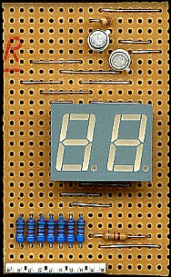
![]() As usual
the board can connect to any full 8 bit port, because the display is common
anode the open-collector pin RA4 will work fine, there's no need for pull-up
resistors or anything - however, RA5 on a 16F628 is an input only, so we
can't use PortA on a 628.
As usual
the board can connect to any full 8 bit port, because the display is common
anode the open-collector pin RA4 will work fine, there's no need for pull-up
resistors or anything - however, RA5 on a 16F628 is an input only, so we
can't use PortA on a 628.
 |
|
 |
|
 |
|